Perkins Diesel Engine Review - ElectroPak Model 404c-22g
aka: HP35105U, 5H3XL2-22 NLC, HP29-1800C
Wiring required to get it running
by Joe Mehaffey
rev 10/1/2012 Release 5
I received a Perkins 404c-22g diesel
engine
from Hardy Diesel to replace my old worn out (200 hours of service)
ChangChai Chinese built diesel engine. Yes.. I know.. 200 hours
life for ANY diesel engine is unheard of. But.. For the ChangChai SAGA, click HERE.
After getting it connected to my MECC-ALTE
EC0-28-L2 (21KW prime, 24KW standby) alternator, I can say that the two
engines are as different in sound and performance as a hammer drill is
to a sewing machine! The Perkins is MUCH quieter, and though it
too is far from "silent", it does not sound like it is going to
shake itself apart. The 29HP (at 1800RPM) engine is a much better match to the MECC-ALTE
EC0-28-L2 alternator than was the ChangChai. I bought the oversize
alternator when the original DADI alternator failed on the ChangChai
system several years ago.
I will note here that as of October 2012, my Perkins Engine has
performed flawlessly now for about 6 years requring only routine oil
change and checks. No faults of any kind.
The Perkins engine came to me in 2006 with no
documentation whatsoever. While the mechanical connection of the
alternator and engine was fairly straightforward, I had
considerable problems getting even basic information on component
electrical connections for the engine. How our Perkins friends
expect
anyone to properly wire the engine controls without Perkins providing
even basic information on what the connections are and how they
function is beyond me.
If anyone has any
additional information, let me know and I will add such to the
list below.
NOTE: As of September 2012, I
have been furnished a complete Perkins Wiring Diagram for the Perkins
Engine connected to the DynaGen GTC300 automatic engine
controller. This Diagram is added at the END of this page.
For wiring, be
sure to use #16 or 18 wire (except as noted otherwise) for all
connections to minimize voltage drops in the wire and insure the
ability to start the engine under less than optimum battery conditions.
The wiring from the glow plug relay to the glow plugs should
be #12 or #14 wire. The wire from the battery post (or from
the battery connection on the starter solenoid) should be #10 or #12
gauge. Use proper through hole (not spade) lugs on all
screw terminals for maximum reliability.
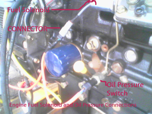
1) The Engine has a 12vdc fuel
control
solenoid that must be activated for engine run and deactivated for
engine stop. This solenoid is attached to the rear of the
injector pump. The
pigtail connector cable out of the solenoid has a two pin connector,
female socket with male pins.
All three of the Perkins connectors are keyed the same so be SURE to
harness them on the engine so they cannot get interchanged.
These are the two wires to the solenoid coil. You must
ground one
wire and connect the other wire to +12vdc power to energize the
solenoid and allow fuel to reach
the cylinders. The wires are not polarity sensitive. See image
below.
In my installation, I used a common ground wire for the fuel solenoid
and for the oil pressure switch and grounded the common connection.
Then the ungrounded fuel solenoid connection is powered by +12vdc
for engine run. Oil pressure switch details are in item #4 below.
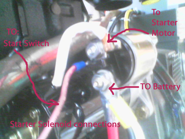
2) The engine has a starter solenoid
and switch mounted on top of the starter motor as is conventional. At first
glance, you will see only two terminals on the starter solenoid.
The first goes to the starter motor and the second is to be
connected to the battery. A third "slide on" terminal is
semi-hidden behind the starter solenoid. This "tongue" terminal is to be
connected to a female slide on socket (furnished in the parts kit) and
is to be connected to the "crank" terminal on the ignition switch or
engine controller. See Image below.
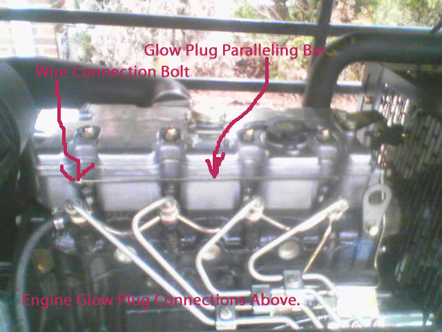
3) This engine is equipped with a glow
plug starting system, one glow plug for each cylinder. The glow plugs are
mounted vertically and are located just above and behind the four
fuel injectors. A sheet metal interconnection bar joins the four
glow plug power terminals. The attachment
point for the glow plug power wire is on the left end of the
stamped sheet metal connecting bar. It is best to feed
this glow plug system with
#12 or #14 wire as the buss draws about 15 amps DC. Normally you turn on the glow
plugs for about 7 seconds before cranking to allow the glow plugs to
assist in starting. To maximize power available for the starter,
the glow plug power is normally turned off immediately before cranking
is commenced. It is not normally necessary (but it is OK) to use the glow plugs
above about 60F. I note that my engine will not start at 40F and lower
without the use of the glow plugs.
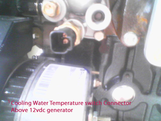
4) The
engine oil pressure and
temperature sensors are SWITCHES and not analog sensors. The
switches CLOSE on out of tolerance conditions. The temp switch
closes at about 205 degrees F signaling engine overheat and the oil
pressure switch closes on low oil pressure. Both switches are two
terminal SPST isolated switches with Perkin's unique two
pin connector. The oil pressure switch is closed when the engine
is stopped and the water temperature switch is open when the
temperature is below 205F. It is intended that these signals be
interconnected with a suitable relay or other circuit to shut off the
fuel solenoid should the engine have either low oil pressure or an
overtemperature condition. See the image below for the
location of the WATER TEMPERATURE switch and the image in item #1 above for the location of the OIL PRESSURE switch.
5) Connector pins and fittings for
Perkins two pin connectors are furnished in the kit with the ignition
switch, air heater and other fittings. These pins are designed to
be crimped onto #16 to #18 gauge wire but you can solder them onto
the wires (carefully with a 47 watt iron) if you do not have the proper
crimp tool. if you solder, you must be careful not to get solder on the
outside of the pin body, else the pin may not fit properly in the
connector body. Use of a crimp tool that FLATTENS the connector
pins is NOT
advised as it can prevent the connector pin from entering the connector
body and seating properly. The proper crimp tool is a "mil-spec"
tool that crimps the pin on all four sides in the area where the wire
enters the pin.
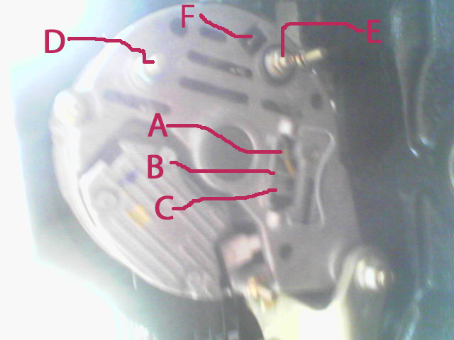
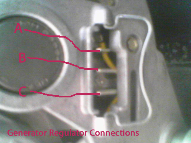
6) The 12 volt automotive
generator supplied with this machine is a six terminal unit but only
TWO terminals are used. The FIELD winding(A) and OUTPUT
terminal(E) are the only terminals used and are shown in the image
below. The OUTPUT terminal(E) is the screw/nut
terminal located nearest the engine core. The FIELD terminal(A)
is the topmost slide on connection terminal.
See picture below for locations. The mating "slide on"
female connector is furnished as part of the
hardware kit along with the ignition switch assembly. Slide on
connector pins can also be found at any automobile parts store. Pins B, C, D, and F are not used.
7) A suitable wiring diagram for the
MANUAL ignition switch( furnished with the kit is shown below.
This is a four position switch. The positions starting from
left are HEAT, OFF, RUN, and spring return START position.
Basically, the switch is
wired so that when the switch is turned to the LEFT, the glow plug heat
is turned ON. Then when you turn the switch to the far right
both the
generator fuel solenoid and and the starter solenoid are
engergized. Then when you release the key, the key springs back
counterclockwise to the RIN position. The Starter Solenoid is
energized in the START
position. Note that with this manual switch system, if you leave
the switch in the LEFT (HEAT) position for a long time you will
probably burn out your glow plugs plus you will definitely run down
your battery. If you leave the switch in the RUN position with
the engine stopped, you will also eventually run down your
battery. For
these reasons, you will be a lot better off to have some automatic
start/run/stop system which will automatically start and stop
your engine and not accidently leave the system in a state to run down
the battery. Two such appliances are described below in item #8..
(Drawing in Work showing manual ignition switch setup)
8) Automatic Engine Starters suitable
for use with the Perkins 404c-22g ElectroPak engine (and similar small
diesel and gasoline engines) are the DynaGen GSC300 and GSC400
controllers and the FW Murphy ASM-170 and Cascade models. The GSC300 model is sold direct by DynaGen/Canada
for about US$190 plus shipping. A wiring diagram to connect the
GSC300 model to the Perkins ElectroPak is shown below. The other
controllers are wired similarly. Controller setup involves
selection of such parameters as start motor run time, restart holdoff time,
glow plug operate time before start, run time after switch off signal, and other
parameters depending on controller model.
(Drawings in Work for GSC300)
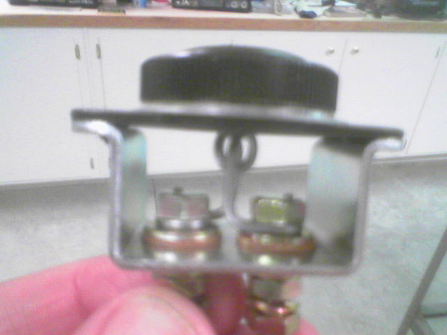
9) The item below looks like
some sort of inlet air heater, but I cannot figure out (yet) where to
put it. I assume it is supposed to be energized at the same time as the
glow plugs.. When I find out more about it, I will add details here.
10) If desired, tapped holes are
available on the engine for separate analog water temperature and oil
pressure sensor installation. You can purchase such auxiliary sensors from almost any automobile parts store.
Below is a picture of the overall engine/generator system with the enclosure side panels removed.
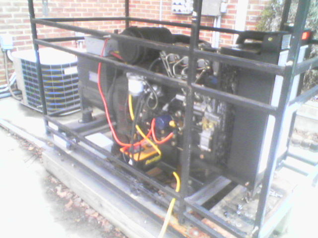
PS> CellPhone cameras are not superb, but for something like this, they get the job done quick and easy.
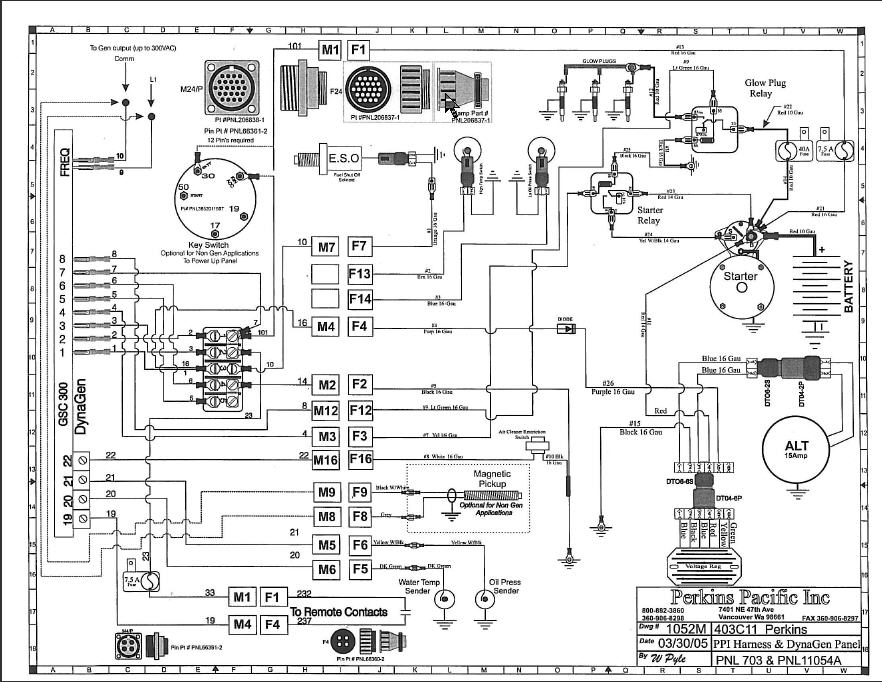
Wiring Diagram for DynaGen GSC300 to Perkins Diesel Engine as of September 2012
The original PDF document can be seen HERE.