The association display tables of
the Cisco APs does not always display ALL of the connected IPs and MAC
addresses alive on the network. The main discrepancy appears to
be when an external wireless client bridge (such as the LinkSys WET11
or the Dlink 900AP+) is used to provide an ethernet-to-radio
bridge for a client computer. In such an arrangement, there
are possibly THREE sets of MAC addresses and IP addresses to
consider. These are: a) The MAC address and IP address of
the LAN card (NIC) in the client computer, b) the IP address
and IP address of the ETHERNET side of the client bride device
and c) the IP and MAC addresses of the WIRELESS side of the client
bridge device. With this array of addresses to choose from,
here is a table showing what is actually displayed by various
devices/software on the Hotspot Network. Note: In this example,
all client bridges (WET11s) and Cisco APs have fixed IP addresses and
all client NICs use DHCP. DHCP scanning by the Mikrotik Hotspot's
DHCP server does NOT cover the range used by the fixed IP address
devices and this may be the cause of the fixed IP addresses not showing
up in the Cisco AP tables. Though why they SOMETIMES show up in
the Cisco association table is still mysterious.
|
IP displayed
|
MAC displayed
|
IP/MAC when Mikrotik Auto MAC Login enabled
|
Device
|
|
|
|
Client WinIPCfg
|
NIC
|
NIC
|
|
Bridge Utility SW
|
WET11
|
WET11
|
|
Cisco Association
|
NIC (sometimes WET11 also)
|
NIC(sometimes WET11 also)
|
|
Mikrotik HotSpot Active
|
NIC (but not if WET11 in circuit)
|
NIC(but not if WET11 in circuit.)
|
IP/MAC of autologin via MAC NIC clients now shown in MT version 2.7.19
|
Mikrotik Router DHCP server leased
|
NIC
|
NIC
|
NIC
|
Mikrotik
|
|
|
|
Notes: 1) This table data is still being developed. More details to follow.
2) The
older WET11 hardware with firmware version 1.54 appears to be
fully compatible with Cisco APs tested here. However, the newer
WET11 hardware with firmware version 2.07 will not link to Cisco
AP342/AP352 units with multiple SSIDs enabled. Ver 2.07 firmware
was supposed to fix this but it did not. Other than this, the
WET11 continues to be a quality, inexpensive, and easy to use wireless
client/bridge unit.
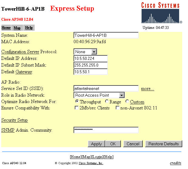
Experiments to Determine the Maximum Range Capability of the AP342/AP352
(Firmware in use is Cisco version 12.04) Maximum Range confirmed
greater than 7.45 miles
Experimental Data gathered thus far as to the maximum range of the
AP342/AP352 is given below. These experiments were run with
a two watt amplifier on each end of the circuit with a combined antenna
gain of 17db for the duration of the tests. This was done so as
to insure to the extent possible that RF signal
level is not the determining factor if data rate slowdowns occur on the
link. There are two
configurations to consider. These are AP optimization set for
THRUPUT (TP) and AP optimization set for RANGE (RG).
Note: The author is an Amateur Radio Operator and is
licensed by the FCC under FCC part 97 to operate at
higher power than that allowed for part 15 equipment for
experimentation on
the section of the Part 15 frequency range which overlaps with and is
shared with the Amateur Radio Service. Unless you hold an
Amateur
Radio License you would be operating illegally and outside the Part 15
and FCC
rules to use power levels not provided by your FCC Part 15 approved
equipment.
Now to the Measurements
1) Out to at least 1.5
miles, the APs will work in TP mode but the speed is down to
2mbps at 1.5 miles with good signals. Changing the setting to RG
mode gets the speed back up to
11mbps at 1.5 miles. I am sure that there is actually a
compromise of the overall data transfer speed, but it is nice to
see the
bit rate return to 11mbps when the RG option is selected. I am
not sure where the optimum crossover occurs, but if you are over
about 0.75 mile between a base station and repeater or between
repeaters, you should try the TP and RG options and see which one
works best for you based on sustained data thruput.
2) Out at 3.7 miles from the base
station (with considerable trees in the way on the mountaintop),
signals were at 42% on the AP342's signal strength display. On RG
option, the bit rate was 11mbps and the system operated very well
indeed. I changed the settings to the TP option and the speed
went to 1mbps and I was (just) barely able to pass enough data to the
base station's AP342 to change the option back to RANGE. So.. I
think that something in the range of a mile or a bit less is the place
where you should change the AP's option from TP to RG.
3) Out at 7.45 miles from the base
station (in the car on local Sawnee Mountain, this time with drizzle
and "moderate" tree blockage in the direction of the base station)
signals were at 43% to 53% (varying) with the AP342 operating in
repeater AP mode in the back seat of my car. The signaling
rate shown in the car and in the AP342 in the base station stayed at 11
Mbps. This was very encouraging. I tried downloading files
and everything went along at the max ADSL rate of about 150Kbytes per
sec. Performance looks good now out to at least 7.45 miles with
the AP342/AP352 equipment. I also tested a Senao client card back
to the base station direct (without use of the AP342 repeater in the
car) and it performed perfectly as expected as well. These tests
were run in the "optimize for RANGE" option both in the base AP and in
the repeater AP. No special selection was made in the Senao
PCMCIA card setup. Transmit power on both ends was set to 2 watts
for this test. Combined antenna gain was about 17db.
4) More distance tests are coming.. Keep tuned.
Data Throughput Tests: Direct and Repeater Modes
Of interest to experimenters is the manner in which data
throughput is affected by range and the various operating modes of
Wireless Data Repeaters such as those of the Cisco AP352/AP342
line. (Note: The performance of OTHER brands and models of
wireless equipment will differ and no generalized conclusions should be
drawn from this limited data.)
The Setups Used:
<at Sawnee Mountain>---------<at Silver City/Ham Tower>--------<inside House>------------------<inside house>
A) Computer #1+amp----7.45 miles----Cisco AP342+amp----300ft----Cisco AP342 (no amp)----20ft----Computer #2
B) Computer #1--5ft--Cisco AP342+amp--7.45miles--Cisco AP342+amp--300ft---Cisco AP342--20ft--Computer #2
Note that the A setup includes Computer #1 Senao PCMCIA card
coupled to a 2 watt amplifier communicating directly to the Cisco AP342
equipped with an amplifier and operating as an Access Point. Then
the Access Point is communicating to a REPEATER Access Point located 300
feet away and then the Repeater AP is communicating to Computer #2
located 20ft from the Repeater AP. The Access Point unit is
located 7.45 miles from Computer #1.
Note:
Test Setup A is operation through TWO repeaters (Ham Tower unit
operates as repeater and so does the one inside the house) and Test
Setup B is operation through THREE repeaters (Sawnee Mtn, Ham
Tower and Inside House). In the B setup, an additional
REPEATER Access Point is inserted in the link between Computer #1 and
the distant Access Point. The rest of the physical link is not
changed.
To be able to communicate (at all) with the central Ham Tower
site, it was necessary to select "optimize for RANGE" in the
express setup screen of the AP342 located at the tower.
However, the other two AP342s would operate fine with the
"optimize for" selection set to either THROUGHPUT or RANGE. We
made tests with multiple combinations of settings to see what
differences were apparent. In addition to the setup with the two
repeaters, we tested setup B (above) which included a direct
connection on the 7.5 mile link to the Ham Tower Access Point.
The data is as follows:
Data transferred consisted of a 2.188 megabyte file. The same
file was transmitted multiple times at each setting as we noticed a lot
of random (and frequent) speed changes on the 7.45 mile link.
Likely this was a result of our location on the mountain where we did
not have a clear and direct line of sight path but rather we were
looking across the brow of a knoll between the car and the distant Ham
Tower site. I suspect the path had a good bit of multipath.
We plan to install a fixed repeater site on this mountain site in the
future and we will run the same tests again to see if thing improve
when we have a better quality radio link.
The Data: Note: TP=Throughput optimized AP setting, RG=RANGE optimized AP setting
Note: Setup (A) operates through TWO repeater APs and Setup (B) operates through THREE repeater APs.
Setup A) Senao/AP
Tower AP setting Repeater Setting Time(s) to Transmit
File Average Thruput
Test 1) Senao
AP=RG
AP=TP
89, 56, 90, 58, 86sec
288654bits per second
Setup B)
Test 1) AP=RG
AP=RG
AP=TP
80,
118, 94, 67, 72 253820
bits per second
Test 2) AP=RG
AP=RG
AP=TP
65, 74, 82,
78
292709 bits per second
Test 3)
AP=TP
AP=RG
AP=TP
55, 68, 53, 100,
63
322714 bits per second
The above data is NOT as high as I had expected. The following are my conclusions at present:
1) The Cisco AP342/AP352 do in fact OPERATE at ranges out to at least
7.45 miles but the data throughput rate is not all that good in the
"optimize for range" position. (It may improve when I am
able to get a better test position with less multipath.)
2) The throughput does not change greatly if just one AP or multiple
APs are placed in RANGE mode and put into operation as repeaters.
3) There HAS to be a better way to get high speed data transport using Wireless over a wide area using repeaters.
4) The throughput just using the Ham Tower unit as an AP and accessing
the internet with the AP in RANGE mode was close to full DSL
speed. While I do not at present know what the "to be expected"
maximum throughput rate for the AP342 used "just as a wide area Access
Point" it appears to be much greater than the speed to be obtained when
the AP342/AP352s are used as REPEATERS in the link.
I will update this data from time to time as more tests are run.
One test will be to setup a computer direct to the Ham Tower AP on the
ethernet side and measure the throughput rate of this "Access Point
Mode" to the remote mountain site. I expect this throughput to be
considerably higher. I also will try and locate a better test
site with less multipath.. But.. The wind and temperature on the
mountain keeps me mostly in the car!
-----------------------------
Here is a quotation from an engineer at Cisco about the AP342/AP352 (specifically) used for longer range work.
"The
'optimize for range' or 'optimize for throughput' setting changes the
data rates settings for both basic and data rates as well as 'slot
times'. What 'range' actually does is to allow a drop down in data rate
(if necessary all the way to 1Mbps) for both data packets as well as
overhead packets. For the ACK timing this will change the hold off
'slot times' to compensate for the longer time it takes for lower data
rate packets to get through. This will permit the beacons and
other packets, required for maintaining association, to get through
easier on the long distance paths.
You got throughput out to 7.45 miles? That's great. But how
many clients were being used at any one time, and what type of traffic
load did you have on the AP at the time? We have tested to over
5 miles, but when we started loading up the AP with traffic, we
noticed packet retries (on the RF link) starting to rise rapidly.
So we have still classified the units as 1 mile capability, based on
11Mb and 25 users, pushing 5Mb of traffic (aggregate) through the
AP. Keep in mind Cisco is
targeting
the enterprise and carpeted office, as well as verticals such as
Healthcare, Education and retail for the majority of our products and
focus. For public access we target hospitality (like hotels) and
hotspots (Starbucks, McDonalds, Airports) so we have not put any large
efforts into longer range public access applications. Hence the
lack of features required for the longer ranges."
Some
Operational Observations of a Cisco based network with a BR352 as the
central node and five AP342/352s operating as Repeater APs
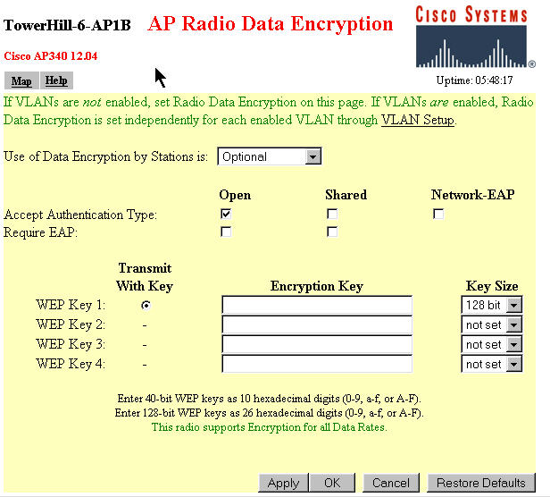
1) LinkSys WET11 model 1 units appeared fully compatible with the Cisco
gear in all modes. WET11 version 2 units are compatible with the
Cisco AP/BR 352/342 units BUT ONLY if you just use a single SSID.
If you use multiple SSIDs in the Cisco gear, WET11 model 2s (with
firmware 2.07 and lower) will not associate with the secondary
SSIDs. (I am told that version 2.07 supposedly does associate
with the primary SSID.)
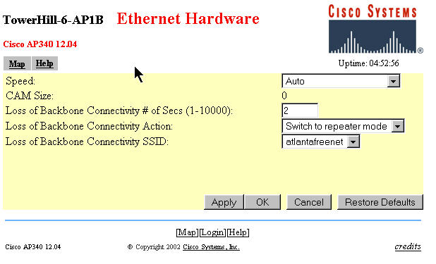
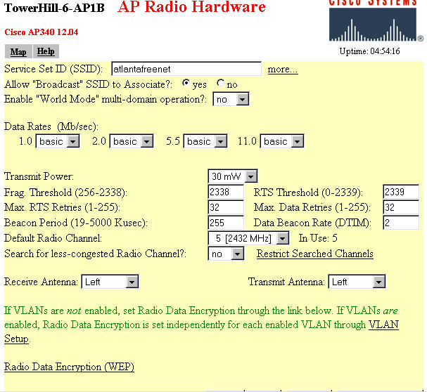
2) The option to "search for a less congested radio channel" is a nice
feature in the Wireless Setup. I originally fixed my network on
channel 5. Six months after installation, I had
interference to my system on channel 5 that virtually made thruput from
the Central Bridge go near zero at times. After identifying the
problem, I set the Central Bridge to allow roaming to channels 3,
4, and 5 if necessary to find a better channel. The system
immediately moved to channel 3. Within 10 seconds or
so, all of the Repeater APs had automatically reassociated and
quickly thereafter all of the WET11s had reassociated and were
working. Some client cards (Cisco, and Orinoco)
automatically reassociated while others required exiting the browser
and other programs and/or rebooting the computer. The system has
stayed on channel 3 and worked fine ever since.
3) To read the signal strength from a particular "downstream" remote
client radio to
AP/BR or from a "downstream" Repeater AP to an "upstream AP/Bridge or
from one Repeater AP to the next
proceed as follows. (Note: Upstream refers to devices closer to
the Root AP or Bridge device which is connected to the wirelan [usually
internet] interface.) Go to the ASSOCIATION TABLE of the
AP or Repeater AP that is the
PARENT for the particular radio in question. Click on the MAC
address for the desired
client or other station which claims this AP/Repeater AP as "parent"
(SELF in the table). Observe "Latest Signal Strength" in percent
in the entry in the right column. This reads the signal strength
AT the "self" or "parent" of the distant repeater's signal.
4) To read the signal strength of an "upstream" Root AP/Bridge or
Repeater at a "downstream" repeater, proceed as follows. Go
the the SETUP table of the downstream repeater. Look for
the NETWORK PORTS line near the bottom of the table. Look
to the right for the diagnostics
link and click on this link. Click on the RADIO DIAGNOSTICS
LINK. Then click on the START button of the Antenna Alignment
Test. Wait about a minute and a table of moment-to-moment signal
strengths will be displayed.
5) I have not been able to get the CARRIER TEST to work on AP342s
with firmware version 12.04. When I try and run a carrier
test, the unit is "locked up" for several hours or more and never
comes back to life or delivers the channel usage chart. I will
try this on a AP352 and BR352 when I get to it.
6) APs have the ability to show traffic to/from the AP in either Bytes
or Packets or both in the association table. (Click on "additional
display filters" and set options.) Bridges can only show traffic
in Packets. I don't know if this is a bug in ver 12.04 firmware
or a limitation of the Bridge perhaps running out of memory or CPU
capacity.
Table of Cisco AP352/AP342/BR352 signal strength readings in Percent converted to dbm
0%
|
5
|
10
|
15
|
20
|
25
|
30
|
35
|
40
|
45
|
50
|
55
|
60
|
65
|
70
|
75
|
80
|
85
|
90
|
95
|
100
|
-92dbm
|
-91
|
-90
|
-89
|
-88
|
-85
|
-82
|
-79
|
-76
|
-73
|
-70
|
-68
|
-65
|
-63
|
-60
|
-57
|
-54
|
-51
|
-48
|
-45
|
-42
|
Does anyone know how the significance of the "signal quality" percentage? If so, please email JOE
**Text
materials in this paper copyrighted 2003, 2004 by Joe Mehaffey, all
rights reserved. Cisco trademarks belong to Cisco Systems.,